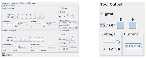
The Monitor I/O tab view.
The Universal-Robot is ideal to use in a small cell for automation because the control besides the robot programming environment also comprises of inputs and outputs which also is easy to program from the onscreen programming environment.
The robot has a standard 8 digital inputs and 8 digital outputs on the controller board inside the cabinet along with 2 analogue inputs and 2 analogue outputs inside the cabinet.
Additional there are also 2 digital inputs and 2 digital outputs and 2 analogue inputs on the tool head itself. This is very elegant because the cabling for these interfaces is routed inside the robot and therefore no external cabling is necessary for these interfaces.
This means that external equipment that is connected to these I/O interfaces like conveyor belts or actuators can be controlled and program from the robot.
If you need more input and outputs then is also easy to extend the number of I/Os by using MODBUD nodes connected via IP network. See later in the manual how to connect and configure a MODBUS node.
To monitor the status of the I/O signals the I/O tab is very useful. Each I/O is represented by a box that is “off” is the signal is “low” or the box is dark if the signal is high.
The out puts can also be manipulated i.e. overruled during commissioning and testing phase in order to check the connected external equipment.

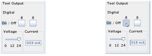
Overall status of I/O. Input 8 and 9 on the tool head is both “high” in this case.

Toggle output on/off by pressing the box at Output 8 is “On”. And it is 24V. The “meter” shows
the output. The device on output 8 is dragging 56 mA.
Digital Outputs are Open collector type. Open collector means that the outputs are implemented to ”sink” and we can say they are ”Active low” because connecting an actuator can be done by applying the supply voltage at the ”far” end of the actuator connections and the other connection to the output terminal – and then when the output is driven low by the programmer – the external device turns on.
If you prefer to have an ”Active high” output – it is also possible – then just apply a ”pull up resistor”. So now the ”far” end of the external device is connected to GND and the other end is connected to the output and a pull up resistor. The pull up resistor is connected to the supply voltage. Now when the output is driven ”high” by the programmer the external device turns on.
Open collector is actually an advantage because it gives the implementation more choices.

The output is not current limited, but if the output is short circuited it will result in a security stop and error messages because of over current detected on an output.
Press “Enable Robot” to restart.

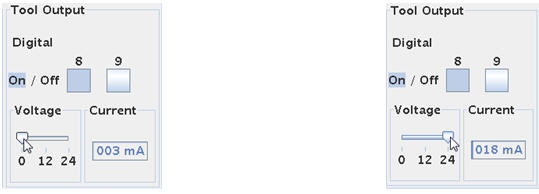
Notice that after an Over current Security stops the voltage is reset to 0V. This has to manually be set back at the desired output voltage 24 V in this case by pulling the bar after the short circuit condition has been removed.
The voltage for the I/O on the tool head can be adjusted to 0 or 12V or 24V from this I/O Tab Screen.
Disclaimer: While the Zacobria Pte. Ltd. believes that information and guidance provided is correct, parties must rely upon their skill and judgement when making use of them. Zacobria Pte. Ltd. assumes no liability for loss or damage caused by error or omission, whether such an error or omission is the result of negligence or any other cause. Where reference is made to legislation it is not to be considered as legal advice. Any and all such liability is disclaimed.
If you need specific advice (for example, medical, legal, financial or risk management), please seek a professional who is licensed or knowledgeable in that area.
Author:
By Zacobria Lars Skovsgaard
Accredited 2015-2018 Universal Robots support Centre and Forum.