Using the Features screen
The Features screen in the ”Installation” screen is an option to define the robots movement to user defined relative points.
These points can be used in the ”Move” screen as from where the robot should move relative to when using the Arrow keys in the ”Move” screen.
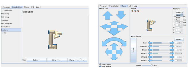
Before we define any new relative points or patterns lets checkout the ”Move” screen.
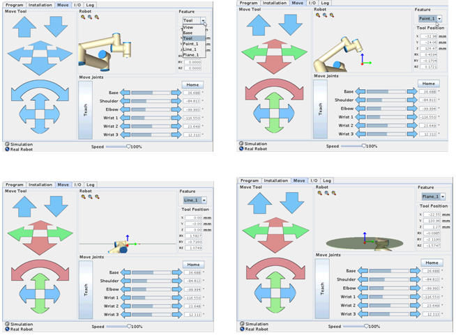
On the top right hand corner is a Feature control. And the robot has already three predefined relative points i.e. ”View”, ”Base” and ”Tool”. By default the View is active.
To explain how the Robot move relative to this point the ”Up” and ”Down” arrow keys are used because they are easy to understand.
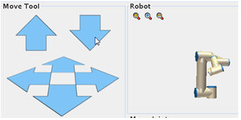
If the robot is mounted like on a table top mounting the ”View” feature relative is like you see (observe – view) the robot and when pressing the ”Up” the robot moves straight up and when pressing ”Down” the robot moves straight down. Choosing ”Base” feature will be the same in this case if the Robot is mounted as table top mounting, but different if the Robot is mounted on Wall or Ceiling or in an angle.
If the Feature is changed to ”Tool” the ”Up” and ”Down” arrows move in the Tool heads core axis. Try and set the tool head in an angle relative to the horizon and press the ”Up” and ”Down” arrows – and observe how the robot now moves in the Tool head axis which is not straight up and down if the head is already in an angle.
Observe the Graphics on this screen which shows the tool head like it is vertical to the horizon, but a closer look will reveal that the base is in an angle and therefore the graphics will show the robot head go up and down, but by observing the robot the head moves in the tool head core plane. This is useful in programming the robot if we are moving relative to an object.
We can also define our own relative points – or line or plane. Go back to the Features in the Installation screen.
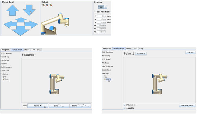
Notice under features is already Base and Tool which are the build in default relative point.
Below press ”Point” which will insert a red ”X” under Base called Point_1. It is red because it is not yet defined. Point on the red ”X” and press it which brings this screen from where you can define (Set this point) like setting a waypoint.
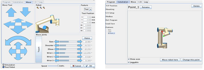
When the relative point has been set (can be a corner of a table or a machine part e.g. a CNC chuck) then press ”OK”.
Now the Point_1 relative point has been defined.
Since we are in this screen then Point at Features again and set a Line and Plane relative points.
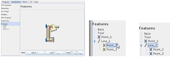
For ”Line” you need to define the two end points of the line.
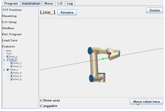
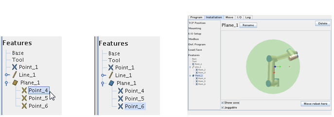
For ”Plane” you need to set three point of the Plane. Choose the ”Show axes” so you can see the axis on the graphics and Tick the ”Joggable” to make it active in the ”Move” screen.
Go back to the ”Move” screen and notice how these three relative points, Line, Plane has been added the ”Feature” menu. Try to choose each of the new relative objects.
Try and go back to the ”Feature” screen in the installation screen.
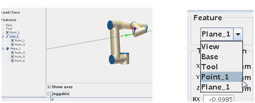
Try and un-tick the ”Joggable”. Go back to the ”Move” screen.
Notice how the ”Line_1” is now missing i.e. that ”Joggable will determine if we have it available in the Feature menu. This Feature is useful when programming the robot and the waypoints are define relative to an object, Line or Plane and it is easier to position the robot.
Disclaimer: While the Zacobria Pte. Ltd. believes that information and guidance provided is correct, parties must rely upon their skill and judgement when making use of them. Zacobria Pte. Ltd. assumes no liability for loss or damage caused by error or omission, whether such an error or omission is the result of negligence or any other cause. Where reference is made to legislation it is not to be considered as legal advice. Any and all such liability is disclaimed.
If you need specific advice (for example, medical, legal, financial or risk management), please seek a professional who is licensed or knowledgeable in that area.
Author:
By Zacobria Lars Skovsgaard